
iPod 4th Generation - Flash Storage Upgrade
...but not how you expect it

By now, most iPod owners are likely aware of the ability to replace the old, spinning-disk drives in their iPods with flash memory cards. Typically this involves connecting a (Micro) SD or CompactFlash card to the iPod’s IDE interface through a converter like the ones made by iFlash.

These tend to work great on the 5th and 6th generation iPods, however are poorly optimised for the 4th Generation. They tend to require cumbersome flex-to-flex adapter cable arrangements, and this results in poor/wasteful volume utilisation.

On the CompactFlash front, it’s not much better. The most common adapter boards on the usual suspects like eBay and AliExpress are these:
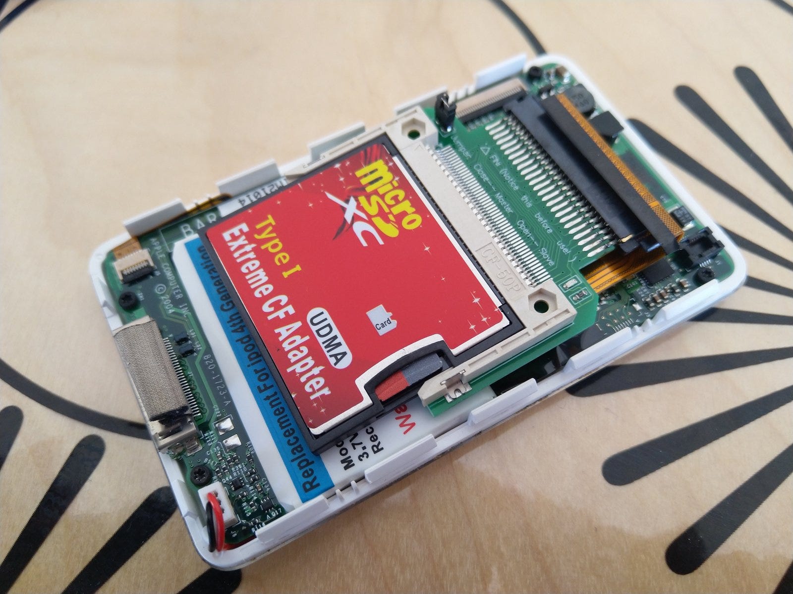
However once again, we have a board that spans almost the entire length of the device, only 60% of which is actually the CompactFlash card.
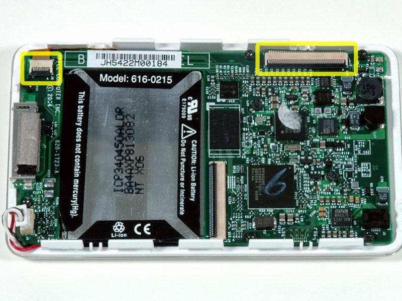
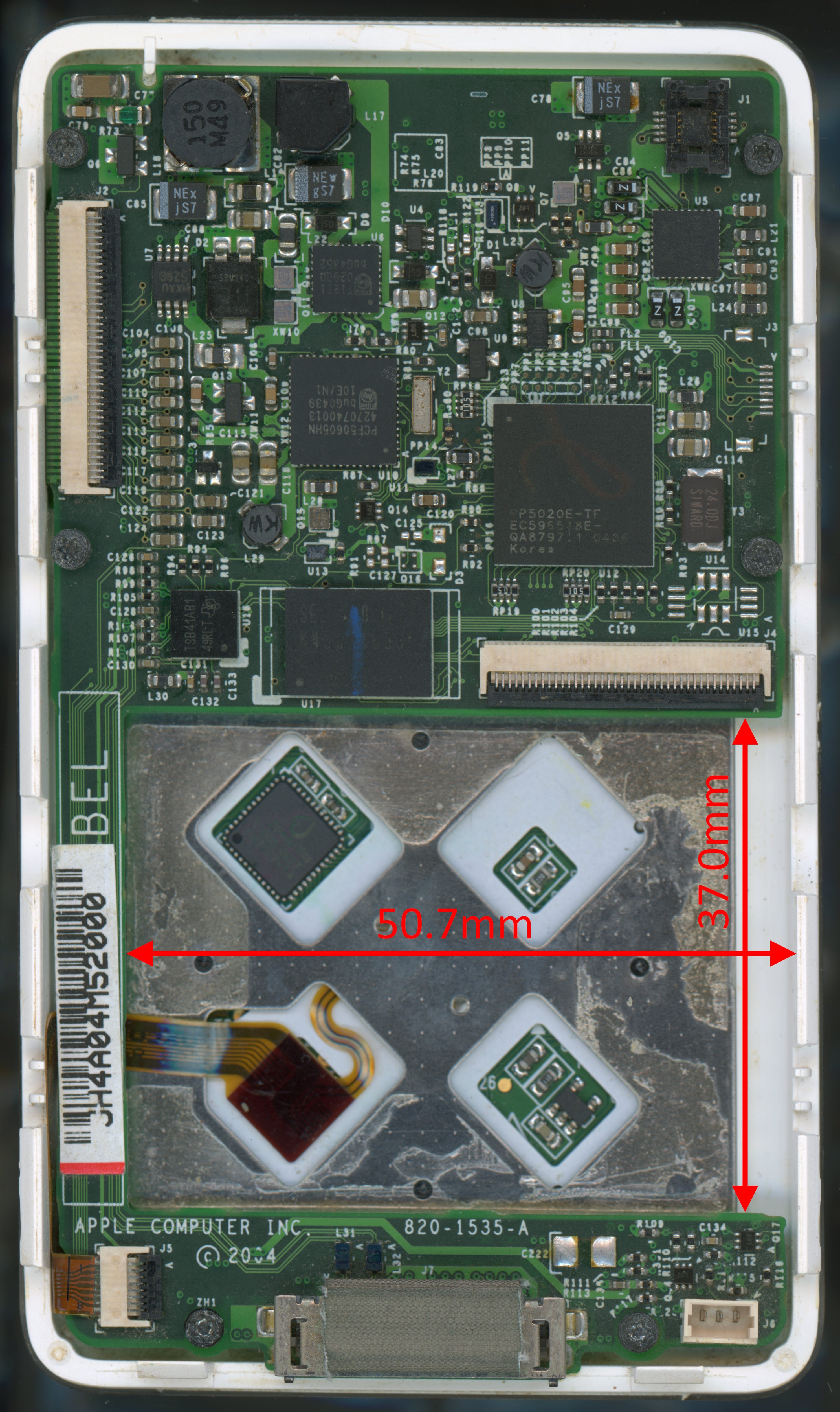
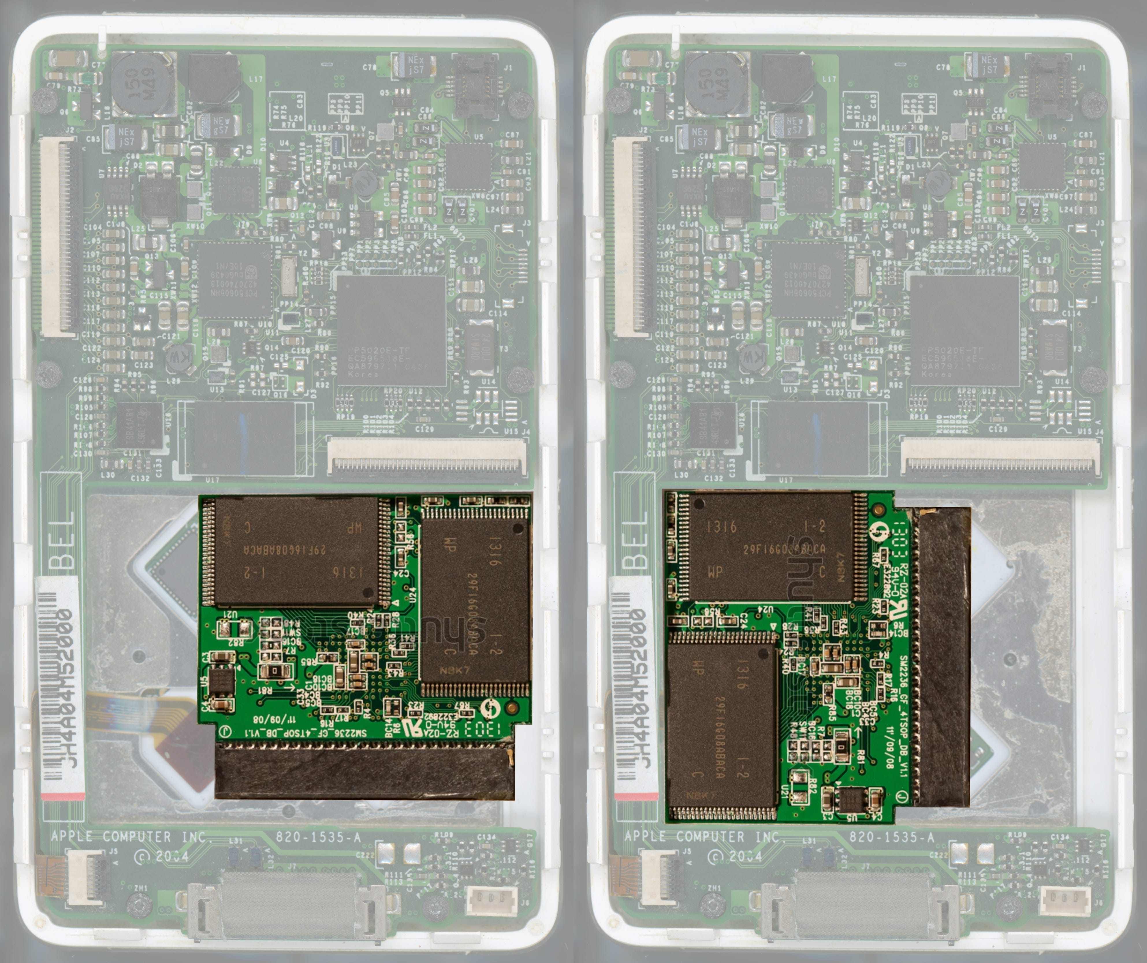
Looking at the internal layout, there’s a cut out in the PCB for the battery that’s just begging to be replaced with a storage module.
The battery cavity measures 50.7 x 37.0mm. Note that the bottom edge of the cut out above the dock connector has three mouse bites (PCB breakout tabs) remnant from the manufacturing panel. If these were filed back to be flush with the edge, the length of the cut out would be 37.4mm.
Looking next at the CompactFlash specification, the maximum dimensions of a Type I card are 42.9 x 36.55 x 3.4mm.
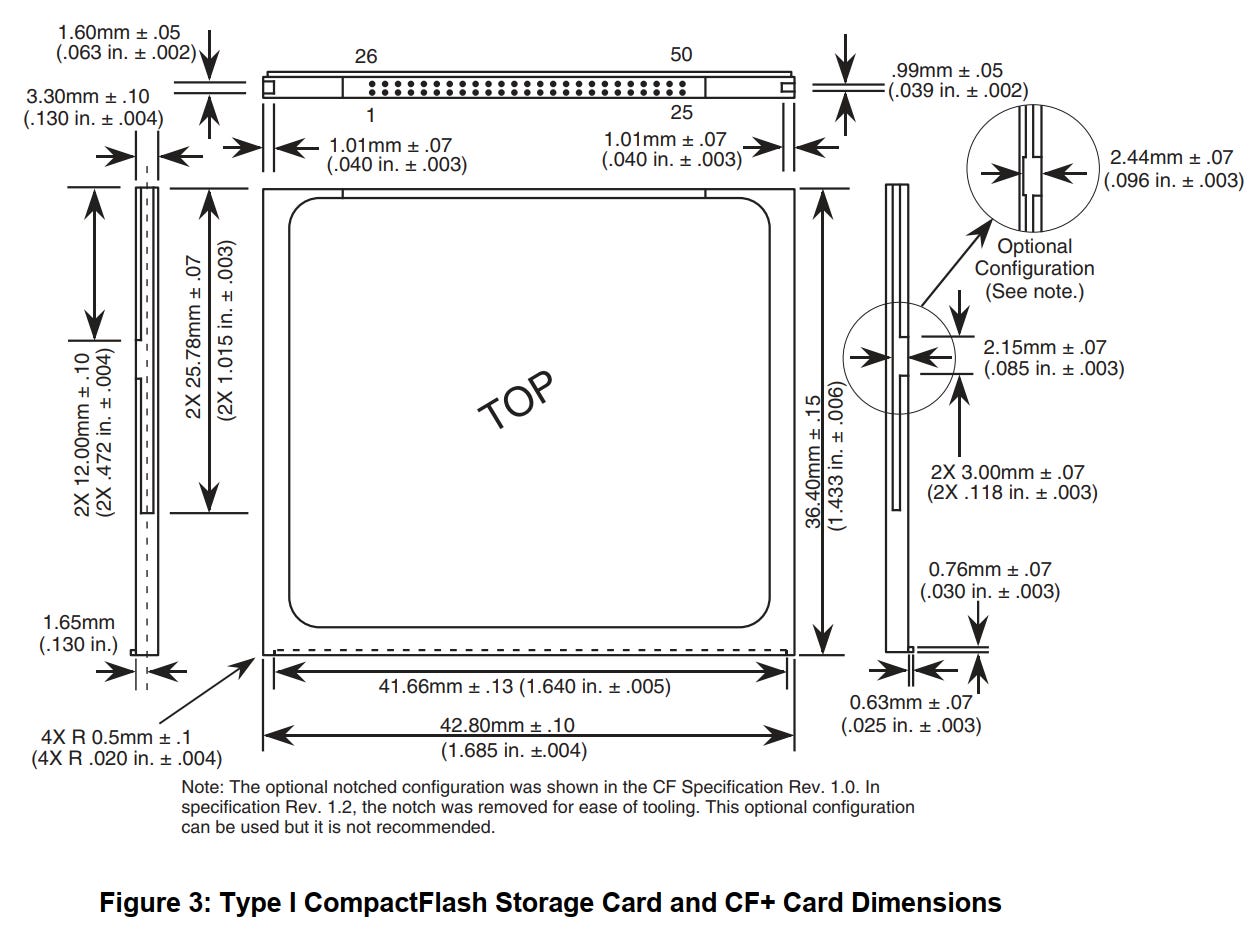
Though this seems like a perfect fit with 0.45mm to spare on the length, we need to keep in mind that we also need to fit a connector and flex PCB in here. The flex thickness is typically no less than 0.3mm with stiffener. This leaves us with 0.15mm for the connector.
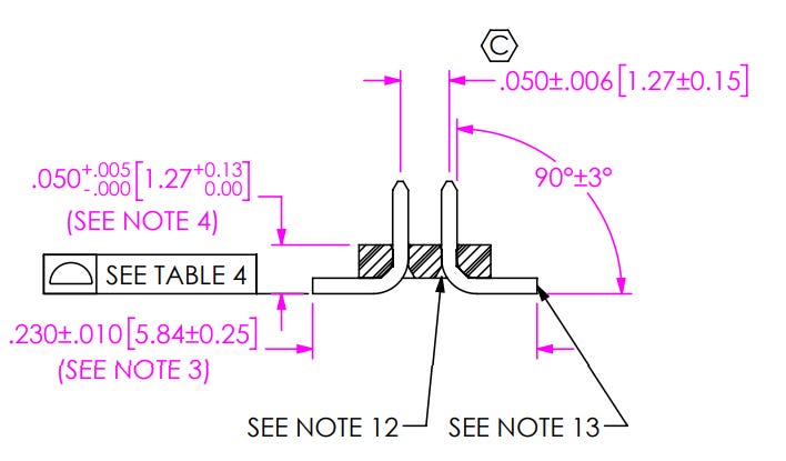
Even if we used a very thin, surface-mount pin header like what Apple used on the original flex cable, the best we can hope for is about 1.27mm mated height, using the Samtec FTS-125.
So all bets are off then, right? Not quite. Although the CompactFlash enclosure is just barely too large, the PCBA contained within it is most certainly smaller.
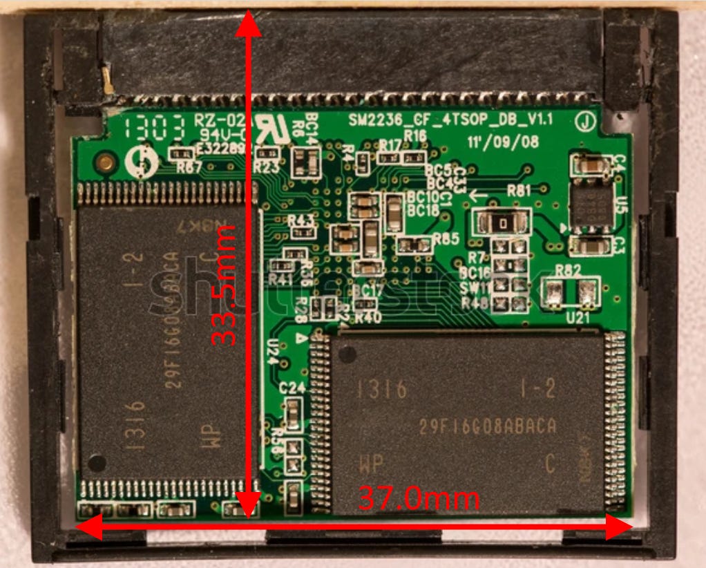
At 37.0 x 33.5mm, the board will now even fit in the portrait orientation, which could prove useful for those that like modding in haptic feedback/Taptic engines without sacrificing volume for a larger battery.
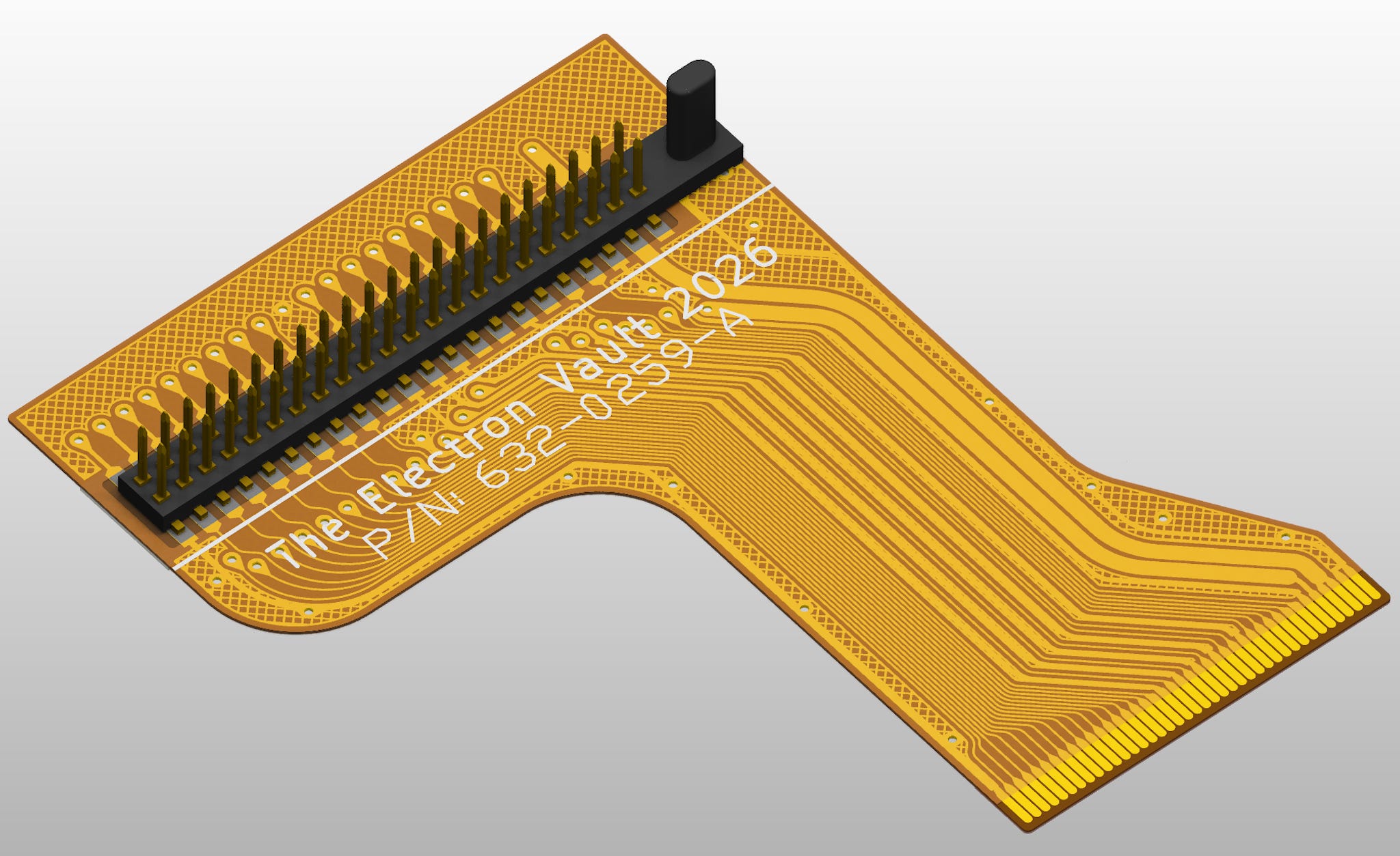
We now have everything we need to draw up a replacement FPC cable for interfacing to CompactFlash.
The source and manufacturing files for this cable are as usual, available on Git here. I extended the apron underneath the flash card to dual purpose the flex as an insulator between the CF card and the metal backing plate for the click wheel. There’s no trackwork in this area though, so if necessary, it can be cut off without affecting function.
In place of a CompactFlash card, you can also use one of these cheap adapters:
The metal plates are clipped into the plastic frame from both sides and can be pried up using a spudger to gain access to the board:
Here’s what the board inside them looks like:
The only thing to be careful of when using these adapters however, is that depending on the adapter card’s design, the MicroSD card may overhang the PCB edge. In the case of the adapter above, this overhang is ~1mm. So with both cards populated, the board width is effectively 39mm, not 37mm. The overhanging card can be spaced using foam tape to clear the iPod main board and any components on it. This foam also maintains a reasonable bend radius on the flex around the header pin pads.
Here is what the assembled flex looks like in-situ:
On the battery side of things, I found these 105080, 5000mAh prismatic cells from the usual suspects are virtually a perfect fit for the ‘thick’ back plates.
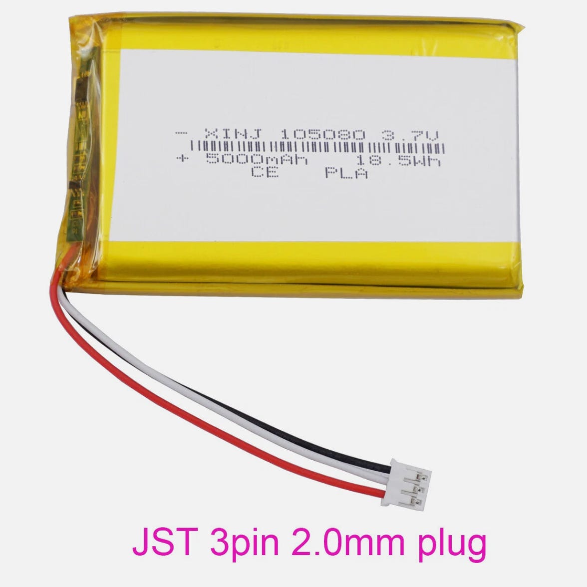
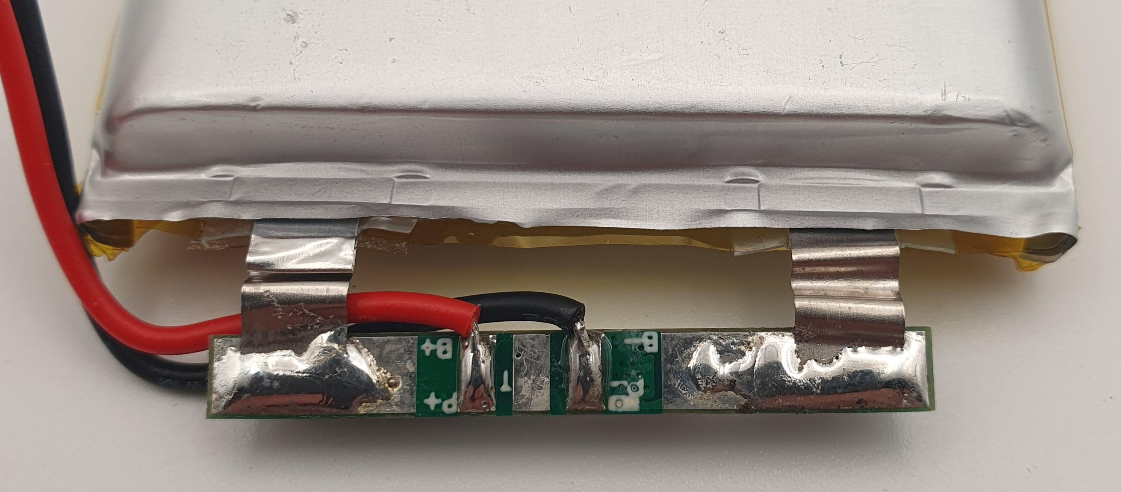
They seem to come with JST PH connectors fitted, in either 2-pin (power only) or 3-pin (power + thermistor) variants. The PCM is the same for both however, so even if you can only find the 2-pin variant, it’s trivial to peel back the polyimide tape covering the PCM board and solder an additional lead to the thermistor pad (I did confirm that my pack was fitted with a 10K NTC, but YMMV). This will need to be done in any case to replace the JST PH cable harness with the Molex PicoBlade used on the iPod.
The battery is fitted on the back plate as shown below using some thin double-sided tape:
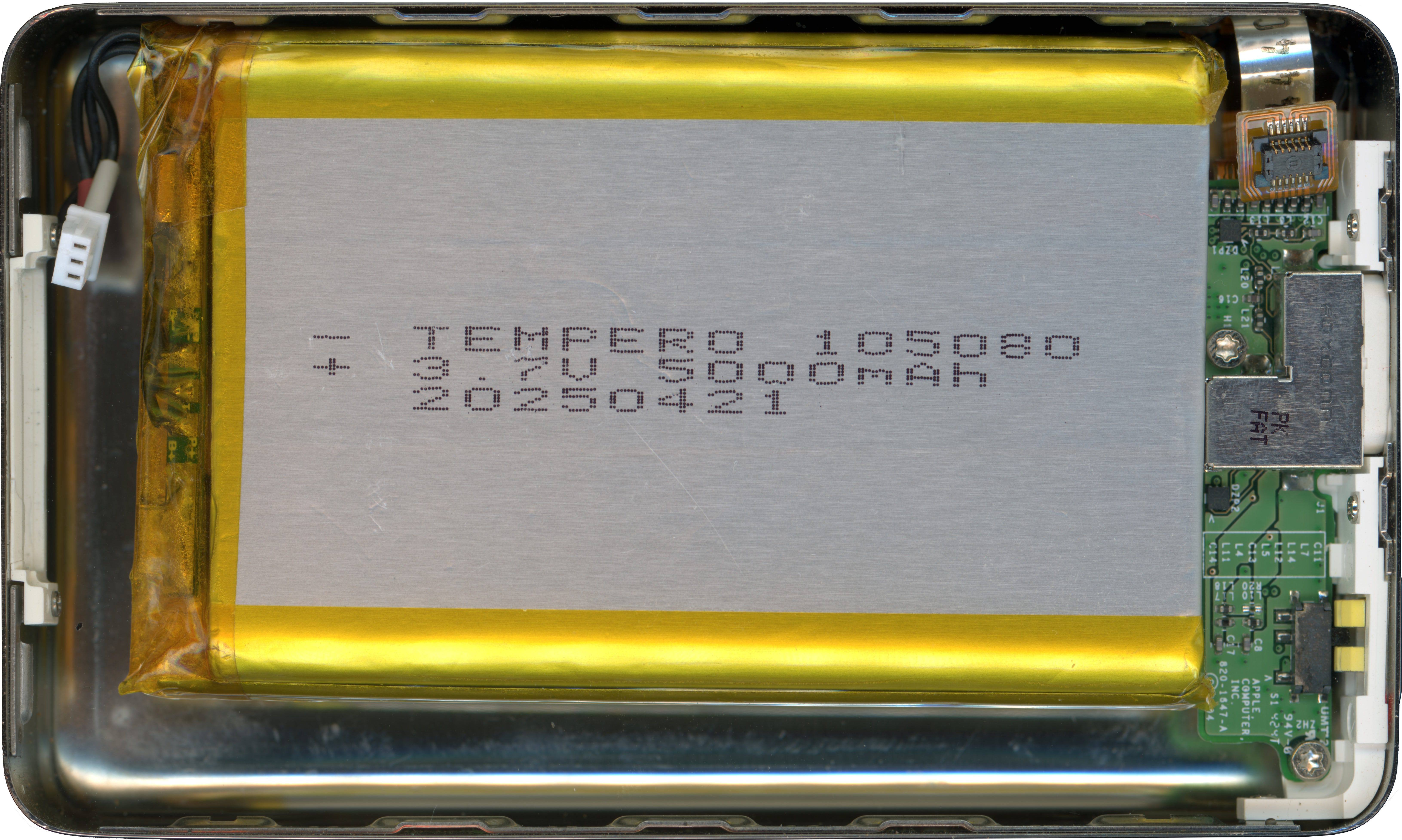
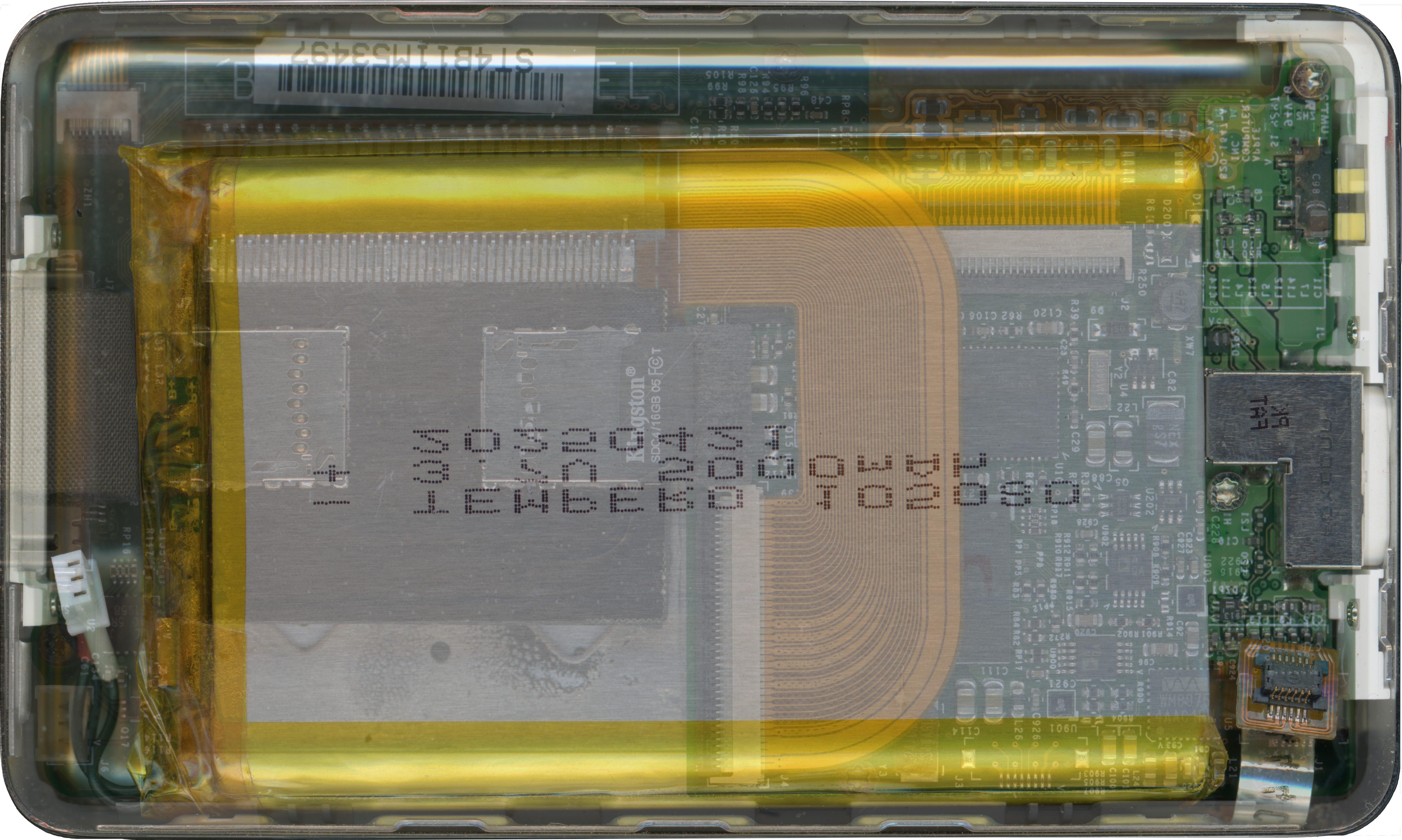
For completeness, here is how it looks overlayed on the main board:
The stock iPod with a thick back plate weighs 6.42oz. (182g). With flash memory and the 5Ah battery, the weight comes in at 6.31oz. (179g). i.e., the hard drive’s weight has essentially been replaced with more battery.
Out of curiosity, to validate these cells were actually 5Ah and not something smaller with a fraudulent label, I decided to run a constant-current discharge test. With a 2.5A (0.5C) load, the expected time to discharge should be approximately 2 hours.
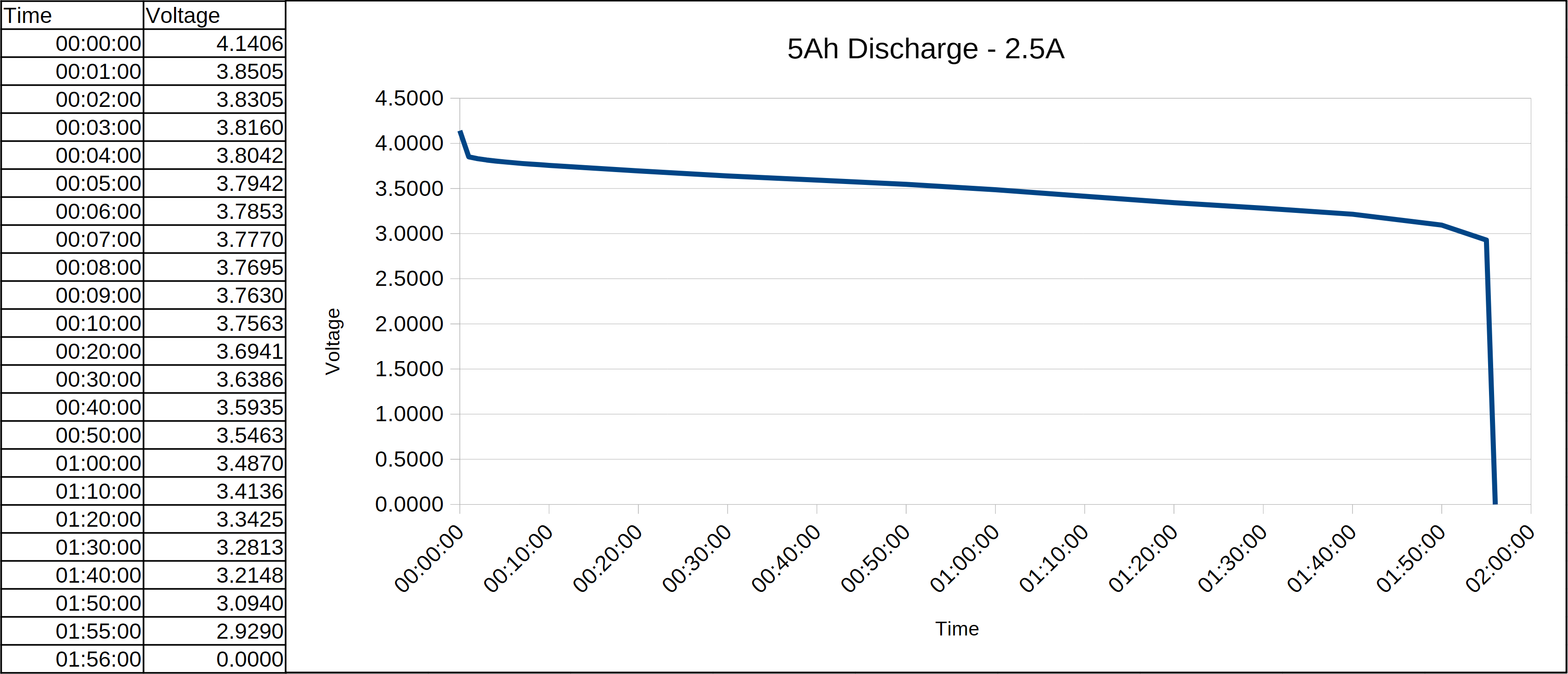
The actual discharge curve matches this to within 5 minutes, reaching PCM UVLO cut-off after approximately 1 hour 56 minutes. Thus, the capacity of this pack is as advertised. Note however of course this is quite an aggressive rate of discharge compared to what the iPod would present. Thus the voltage drop over the battery leads has a non-negligible effect on the measured voltage. That is, the actual cell voltage may be 50-100mV higher than what’s shown on this plot.
fantastic looking adapter, I will try to get one. How do you go about learning how to convert between HDD and CF? are there pinouts available? I've always wondered how this process goes