
iPod Video 5th Generation Click Wheel

Introduction
This page documents the reverse-engineering of the connector pinout and protocol of the iPod Video Click wheel.
Electrical Interface
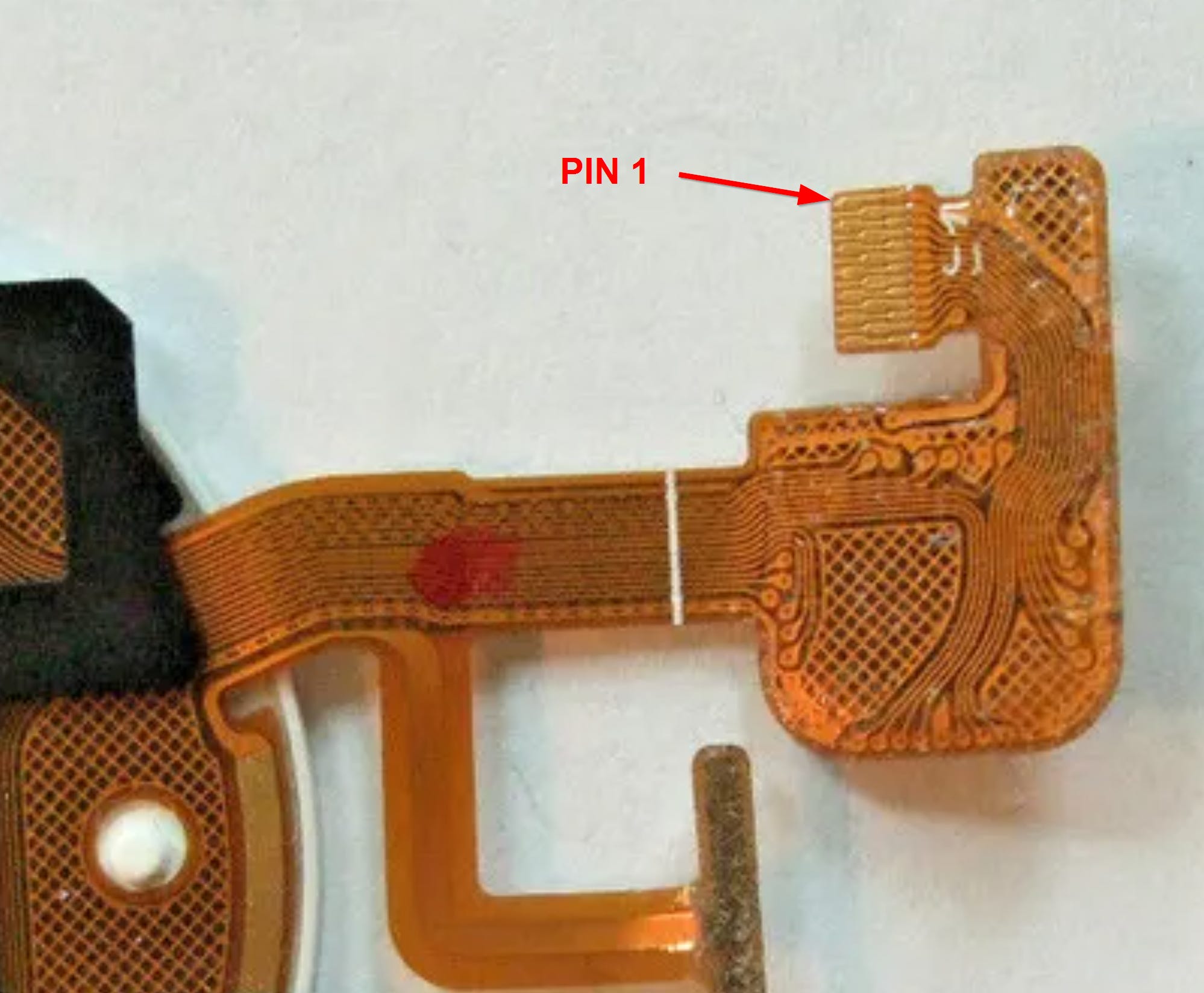
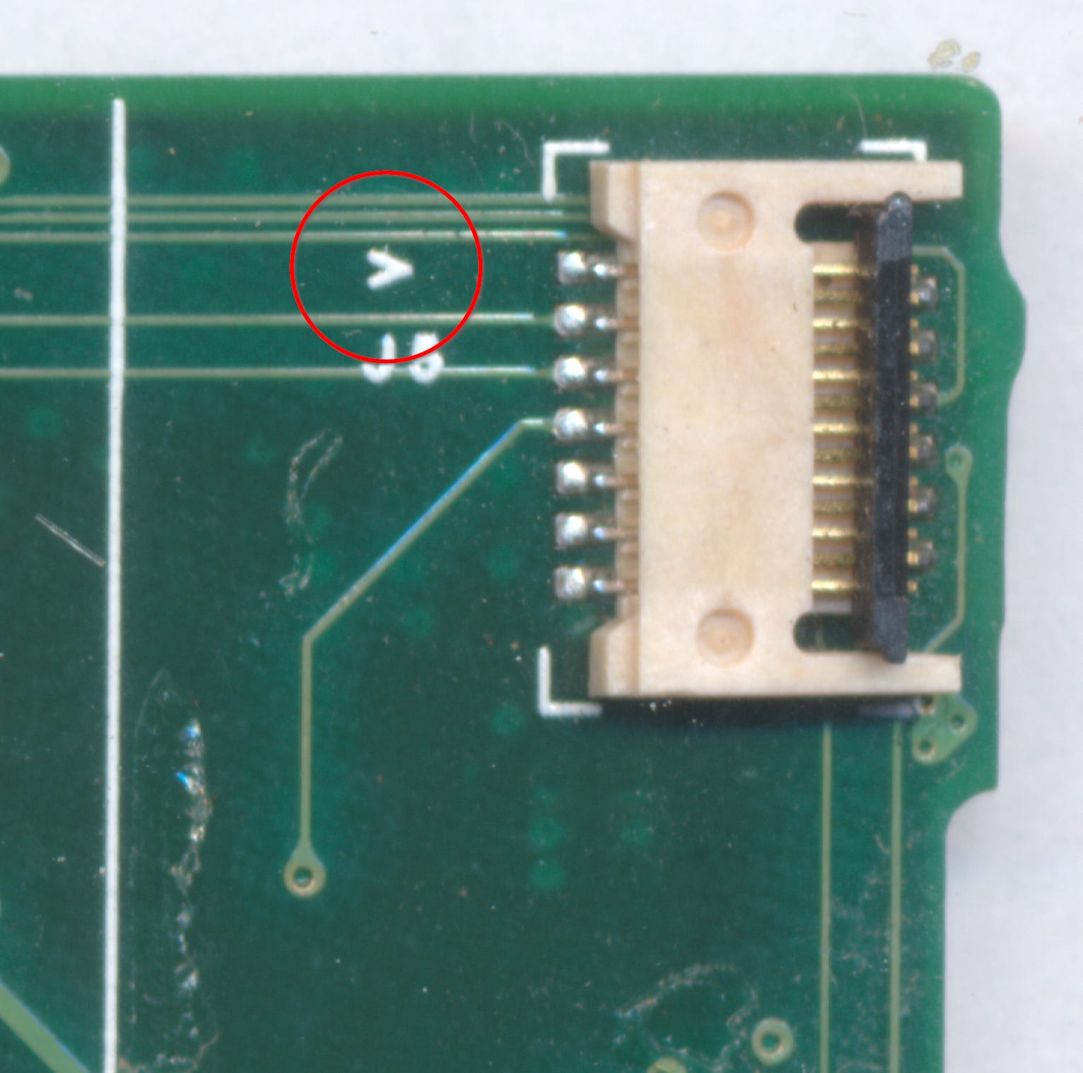
The 5th-gen click wheel interfaces to the main board via a 13-position 0.3mm pitch FPC connector. Pin 1 is indicated by the caret on the silk layer just above ‘J1’, which also matches pin 1 on the main board side. The connector used on the main board is a DDK FF12-13A-R11AL-3H, though there are plenty of alternates sourceable from Digi-Key and the like.
Below is the crude breakout used to probe the Click Wheel.
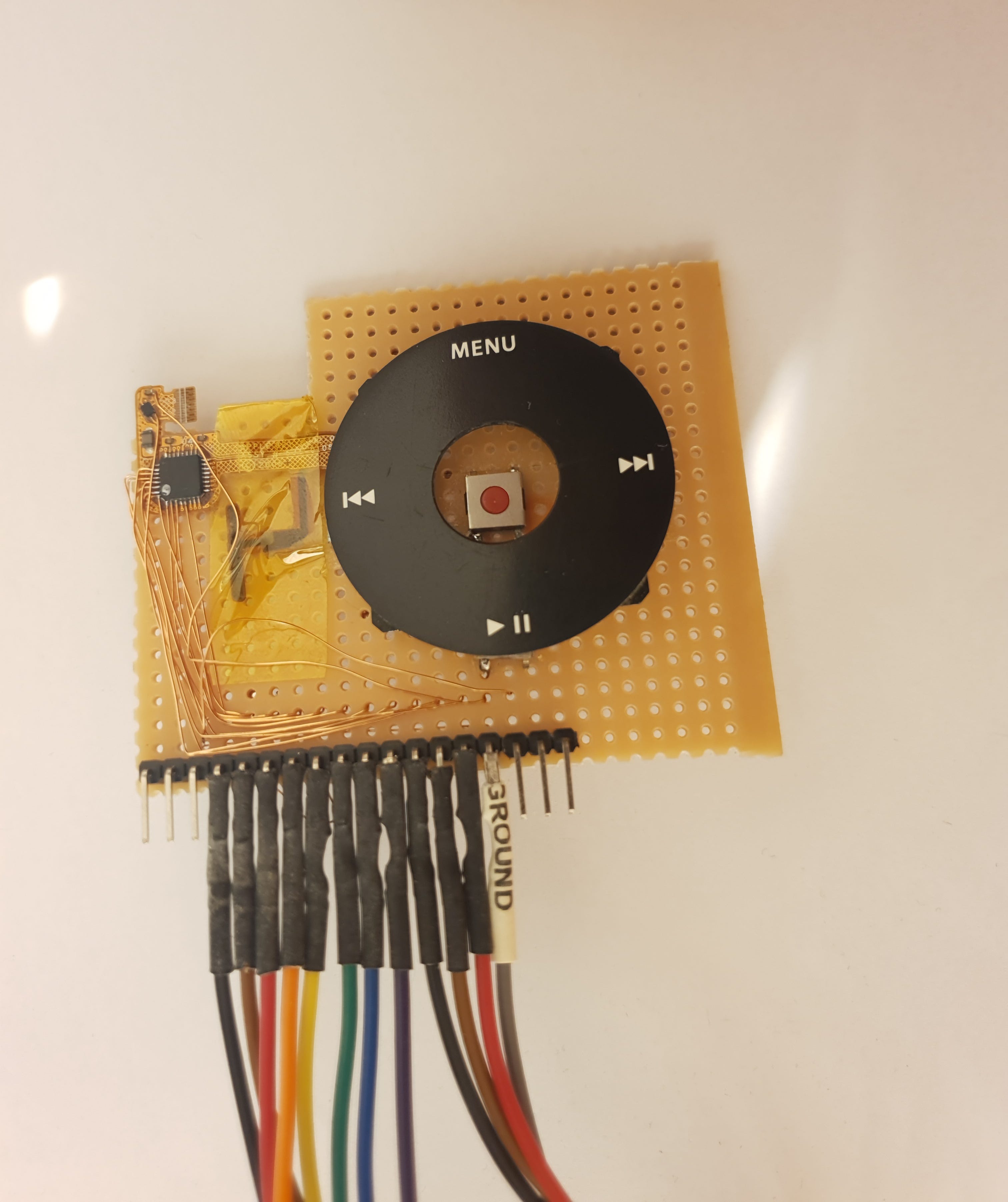
The Click Wheel is implemented on a Cypress PSoC 1 mixed-signal SoC; part number CY8C21434-24LFX. I tried to dump the configuration using a MiniProg3, however unfortunately the flash protection flags have been set. Therefore, through inference of the measured signals and the connections on the main board, below is my best guess at each pin’s function.
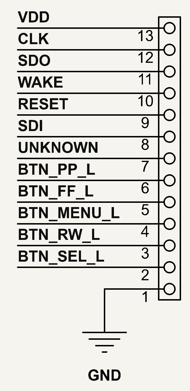
13. VDD
Self explanatory. This goes straight into an LDO (U2) on the FPC. This appears to be a 4-DFN-style with a body dimension of approximately 1.4mm x 1.1mm and a top marking ‘T’. I was not able to locate its part number, however the output voltage (which powers the Cypress CY8C21434-24LFX) is 3.0V. Not knowing the part number, I’m not sure what maximum input voltage it can tolerate, however doing a quick search on Digi-Key (still couldn’t locate it even after trawling the filters) for 4-lead LDOs with a fixed 3V output shows a minimum max-input of 5.5V. An additional data point is that the Click Wheel is powered off the iPod’s system rail, which can be as high as 4.75V if connected to FireWire. So, you can probably safely power this from 5V, but this is suggested without any guarantees.
8. SDI
I originally thought this was a data enable line, as the only way I would get a clock on pin 12 while interacting with the wheel was if I pulled/tied this pin high. However tied high, the SDO pin (11) would stay idle, despite clock presence. While experimenting, I tried doing various things with this pin, which included shorting it to SDO. Once I did, I was able to get data to appear on SDI and SDO. These pins however are not shorted on the main board; they both go to separate pins on the PP5021C. There is also an 18k pull-up like SDO. Therefore I think this is either a data input to the Click Wheel, or an active loopback used as a crude acknowledgement mechanism. I’ve only tested shorting to SDO. I don’t currently have a working iPod to be able to verify what actually happens on this pin during normal in-situ operation.
11. SDO
As mentioned previously, this is the data output. The Click Wheel outputs a 4-byte frame to describe report interactions with it. The format/protocol is covered in the next section. This line is open-drain drive and is pulled up through 18kOhms on the main board.
12. CLK
Self explanatory. Like the data line, this is also open-drain drive and is pulled up through 18kOhms on the main board. Clock frequency is approximately 53kHz and generated by the PSoC.
10. WAKE
I had a hard time coming up with a name for this. I ended up going with ‘WAKE’ since I believe that’s what the its purpose is. This line pulses high for 20ms when either Menu or Select are pressed. Only these two buttons will wake the iPod up from deep standby (boots with Apple logo) - hence the name ‘WAKE’. The pulse occurs only on assertion of either button, not on release/deassert. Interestingly though, if you push either of these buttons alongside any of the other buttons, you get a second pulse on release of one of the two pressed buttons (also happens if you press Menu and Select). Not sure if this is intentional or not but an observation nonetheless.
9. RESET
This is the signal that triggers the hardware reset when Menu and Select are held for 5 seconds. Once triggered, the reset line will assert high for 500ms before returning low. I also tested press and hold of Play/Pause (sleep gesture) to see if that caused any activity on this or any other line - it didn’t. Another fun detail is that simply pressing the physical Menu/Select buttons is not sufficient to trigger this reset. The PSoC also has to sense a finger on the Click Wheel. i.e. if there is no capacitive input, the reset pulse won’t trigger. Not sure why they did it this way, possibly to mitigate the potential for accidental resets when pocketed or stowed in a bag?
7. UNKNOWN
I’ve not for the life of me been able to work out what this line does. It doesn’t appear to influence the other pins in any way that I’ve been able to find. It does connect to the PP5021C. It’s pulled up via 18k on the main board like SDO and SDI. Purpose TBC.
2-6. Button Inputs
To my initial surprise, the buttons on the main board are digitised by the Click Wheel. The don’t connect to any of the main board-side ICs. However after discovering everything written above, it makes sense why. These inputs are active-low and don’t require external pull-ups.
Protocol
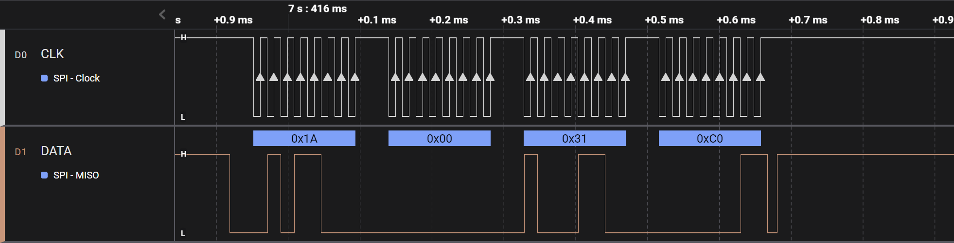
Data are organised LSB first, clocked out by the PSoC at approximately 53kHz. All frames consist of 4-bytes.

The pack attached above contains the files shown below. Simply download and rename the .cbz extension to .zip to extract.
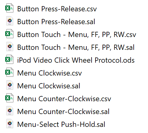
These are all of the raw Saleae capture files (download available here for free, hardware analyser not required), as well as the CSVs exported from them. Additionally, the iPod Video Click Wheel Protocol.ods (spreadsheet) file displays the various data transmitted in a more readable manner. The spreadsheet also assigns names to each bitfield in a summary page. This is shown below:
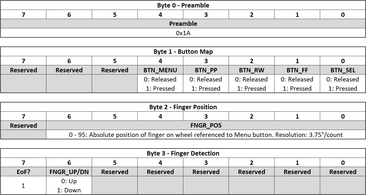
As can be seen from the captures, the first byte is always 1Ah, thus I have designated it to be a preamble.
The second byte is a simple bitfield for the tactile button states. Self explanatory - 0 for released, 1 for pressed. As it’s a bitfield, multiple button presses are supported. This can be seen working in the Menu-Select Push-Hold capture.
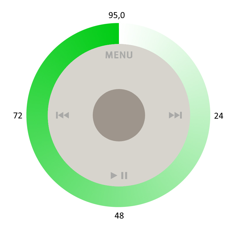
The third byte conveys the absolute angular position of the finger on the Click Wheel on a scale of 0 - 95 (weird, I know). This equates to a resolution of 3.75° per count. The count increases in a clockwise manner, and 0 is referenced to the Menu button.
The fourth and final byte seems to only contain a finger up/down indicator and what seems to be an End-of-Frame marker. I suspect this is the case given that it still reports 80h (bit 7 set) even if there is data sent with no capacitive stimulus, which you can do by actuating the tactile switches only. This is demonstrated in the Button Press-Release capture, where no stimulus is taking place except for the tactile buttons - the Finger Position byte is always 00h, and the FNGR_UP/DN bit is always 0.
Implementation
Though for now there are no drivers provided as part of this article, the implementation should be fairly straightforward on most platforms. Standard peripheral options available to choose from on most platforms are I2C, UART, and SPI.
I2C
Although this is electrically the most similar (open-drain), the protocol is nothing alike. For starters, the data is not bidirectional, and the clock is driven by the ‘peripheral’. Even if the MCU/MPU were to be configured as a slave, the hardware-level expectations of the I2C peripheral, such as start/stop conditions, address matching, ACK/NACK, and not least the clock speed, likely rules out I2C as being appropriate.
UART
The main limitation with UART is that it’s unclocked. This leaves it open to bit errors with baud jitter/mismatch. It will probably work in most circumstances provided a stable reference clock with the dividers/multipliers configured to minimise error. This does however of course assume that the clock of the Click Wheel is precise/stable, which it isn’t/can’t be. UART is otherwise perfectly suited to receiving arbitrary byte streams with minimal overhead, on which more complex protocols can be built. If your platform is fortunate enough to support USART, this would be an ideal fit. Unfortunately not all platforms support it.
SPI
This really is to USART as Pepsi is to Coke (in this circumstance) - in the latter’s absence, the former ‘will do’. It’s functionally identical to USART, only you’ve got a CS signal which you’ll need to configure to be ignored, or tie low on the board if your platform doesn’t permit it. Other than this, it’s fairly straightforward - just configure the SPI peripheral for slave operation, and interrupt on or DMA the bytes as they’re clocked in.
There will need to be a state machine or similar wrapped around whichever solution you implement to ensure the frames are only decoded when all four bytes are received. However the definition of this is beyond the scope of this article. Protobuf could be a good way to keep things organised/readable.
That’s all for now. Leave a comment below if you spot any errors or have any suggestions for improvements.