
iPod Video 5th Generation - LCD

I stumbled across some great work done by Mike Harrison of Mike’s Electric Stuff, in reverse engineering the physical interface of the iPod Video’s LCD here. He’s done essentially all the hard work in identifying all the critical signals required to talk to this panel, but hit a brick wall in identifying the controller itself.
I had a damaged panel in my parts bin, so I thought I’d close the loop on trying to identify the controller. Funnily enough, the controller I ended up identifying was one Mike actually eliminated from consideration. I’m not sure what made him eliminate it, though I speculate it’s because the data frames he was seeing on the scope didn’t match up with the datasheet. However I think it’s worth another look given some of the similarities I’ve found.
To find the controller, I only needed to do a few things:
Melt the rear side of the LCD laminate to get a clear view of the Chip-On-Glass (COG) controller through the LCD glass.
Measure the size of the COG.
Recognise that the panel was 320 x 240 resolution.
Some informed brute-force searching.
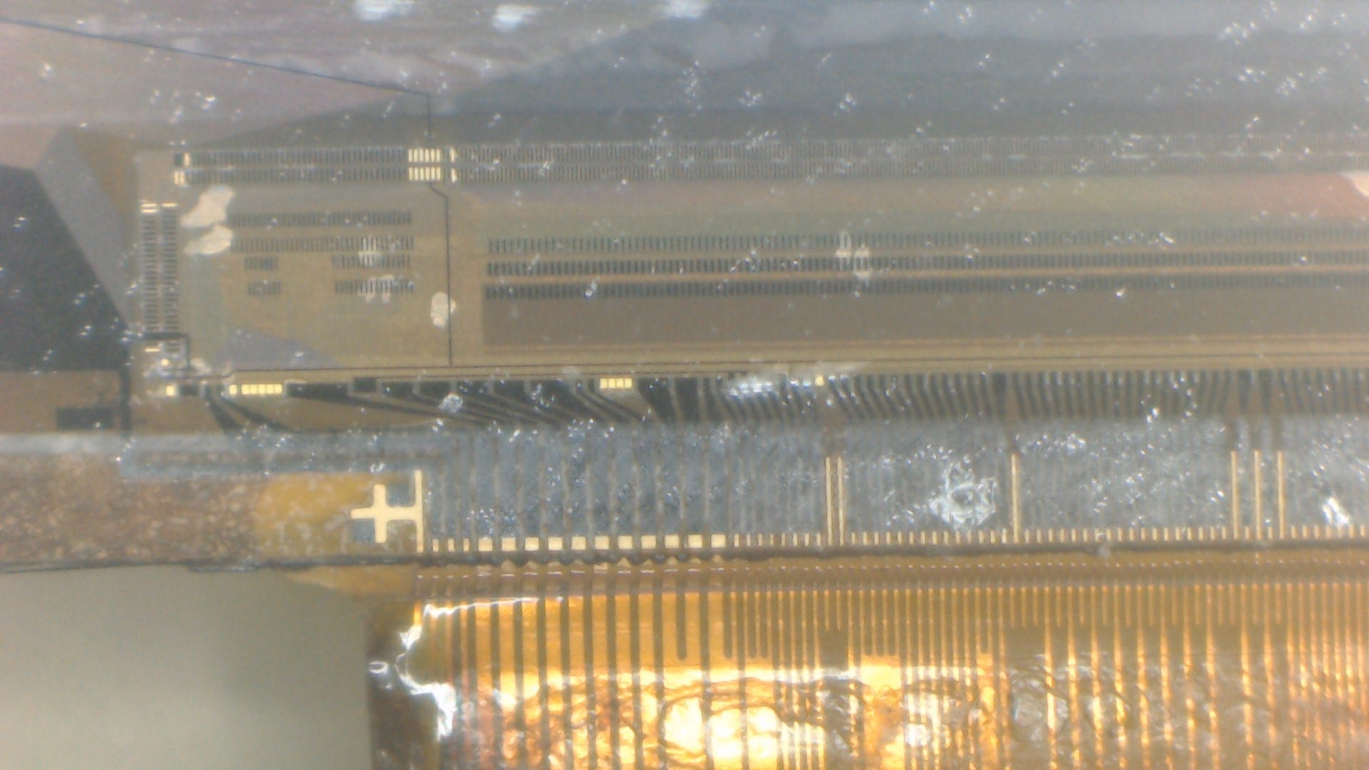
Let’s start with number 1. Here’s what the rear side of the COG looks like with the polariser (and whatever else is in the laminated stack) removed:
Some close up pictures of the die:
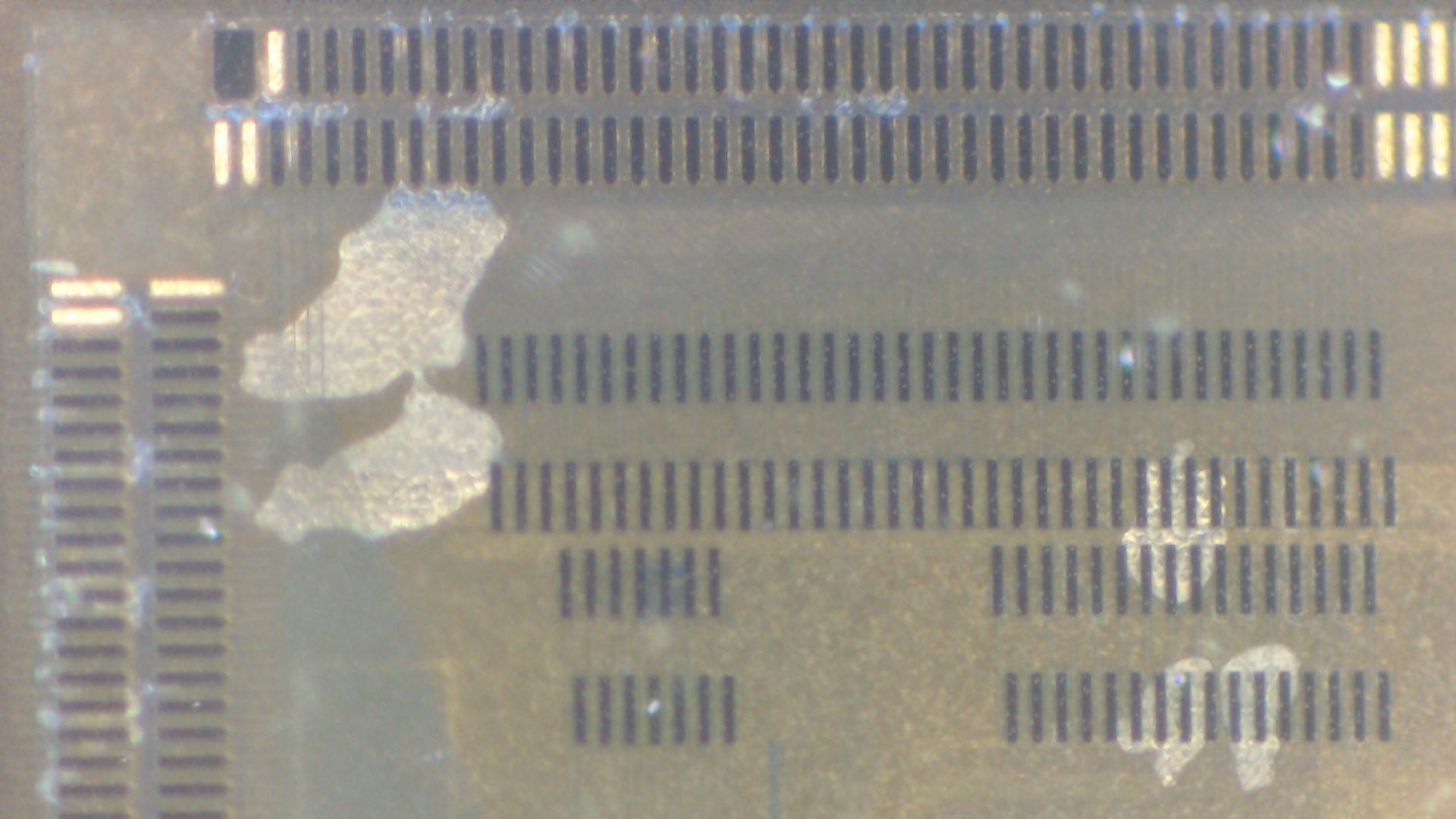
Next I measured the physical COG die size with callipers, which came out to be around 26.77 x 2.3mm. With this information and the resolution, I could then do a brute-force search for COG 320 x 240 "chip size" "2.XXmm" changing the value of XX until I got a hit.
Before long, I found the Epson S1D19122, which was specified nominally at 26.82 x 2.25mm. The first green flag was the similarity of bump shapes. Notice the arrow-shaped profile in the above close-up images.

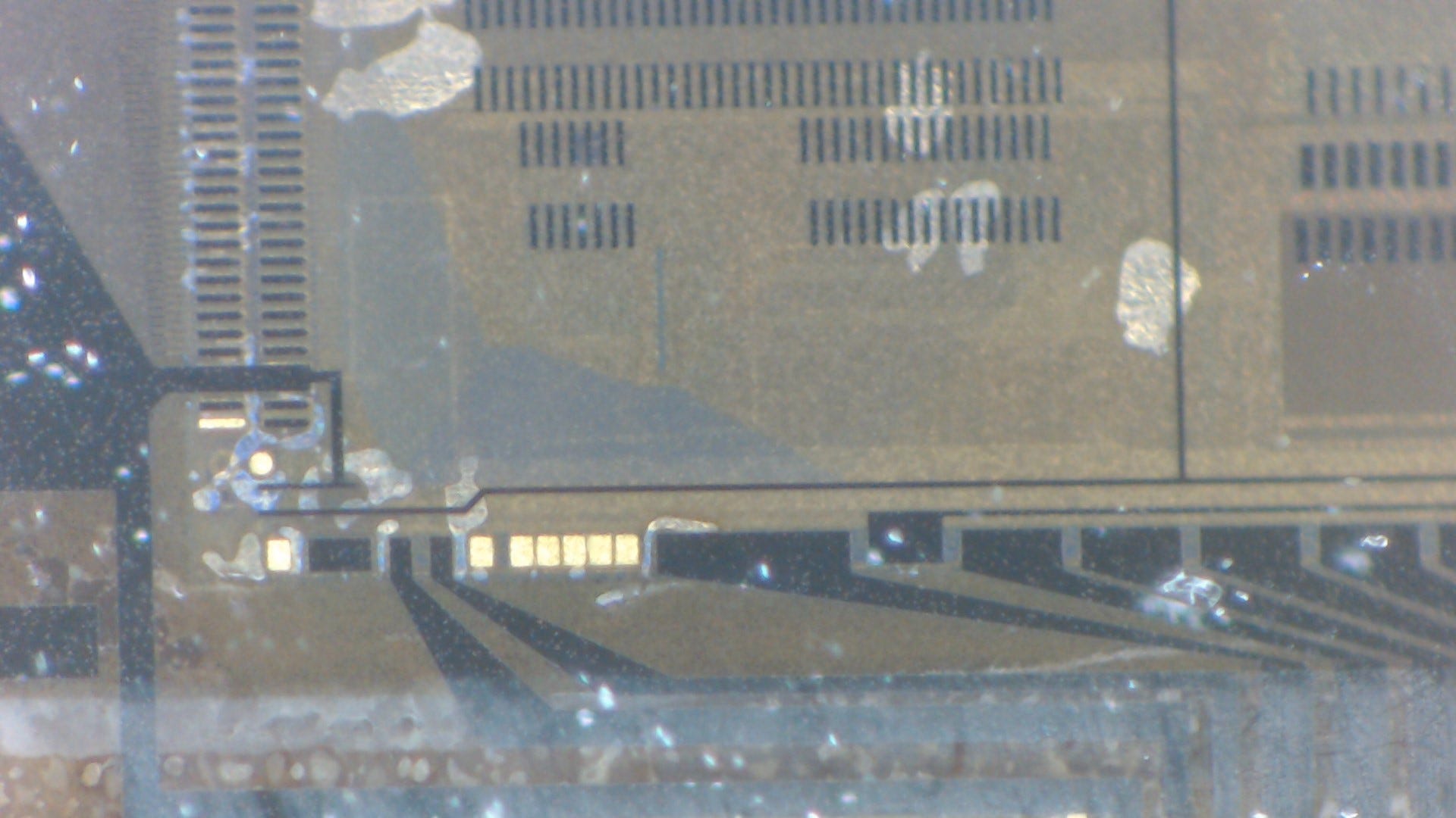
To gain a bit more confidence we’ve identified the correct controller, we can compare the metallisation layer (traces) on the glass to the purported pinout of the COG. Here’s a small section in the pin 1 corner up to the boost charge pump capacitor pads (C11, C12). As we can see, more than a plausible match.
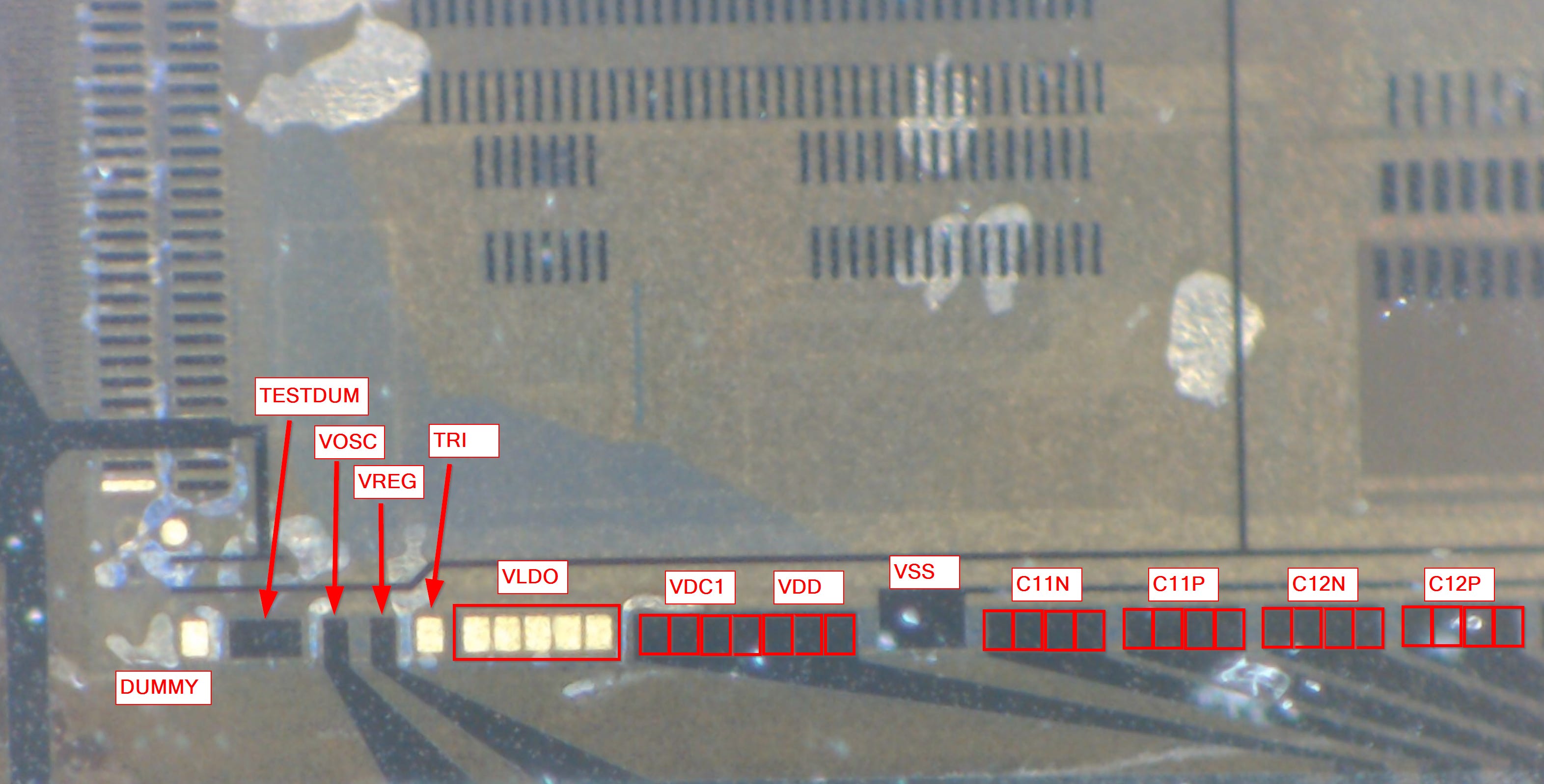
We can then go ahead and map out the reset of the LCD flex based on the pinout of the COG.
Some additional notes:
VSYNC, HSYNC, DCK, and ENA are unused and connected to VDDI/VCORE.
IOVSEL is grounded.
MPUSEL is grounded; P/S is connected to VDDI/VCORE.
LCPOS0 is connected to VDDI/VCORE; LCPOS1 grounded.
INISEL and RESSEL are connected to VDDI/VCORE.
TMONI, OSSEL, and OS1 are grounded.
IF16BIT is connected to VDDI/VCORE.